- 您现在的位置:买卖IC网 > Sheet目录1903 > AT89C51ID2-RLRIM (Atmel)IC MCU FLASH 8051 64K 5V 44-VQFP
76
AT89C51ID2
4289C–8051–11/05
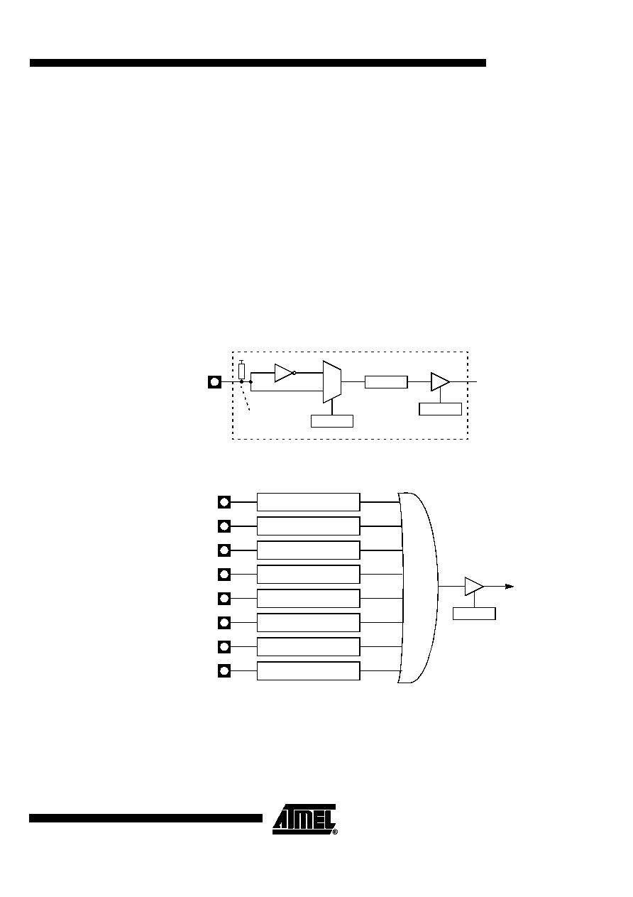
Keyboard Interface
The AT89C51ID2 implements a keyboard interface allowing the connection of a
8 x n matrix keyboard. It is based on 8 inputs with programmable interrupt capability on
both high or low level. These inputs are available as alternate function of P1 and allow to
exit from idle and power down modes.
The keyboard interface interfaces with the C51 core through 3 special function registers:
KBLS, the Keyboard Level Selection register (Table 61), KBE, The Keyboard interrupt
Interrupt
The keyboard inputs are considered as 8 independent interrupt sources sharing the
same interrupt vector. An interrupt enable bit (KBD in IE1) allows global enable or dis-
input has the capability to detect a programmable level according to KBLS. x bit value.
Level detection is then reported in interrupt flags KBF. x that can be masked by software
using KBE. x bits.
This structure allow keyboard arrangement from 1 by n to 8 by n matrix and allow usage
of P1 inputs for other purpose.
Figure 27. Keyboard Interface Block Diagram
Figure 28. Keyboard Input Circuitry
Power Reduction Mode
P1 inputs allow exit from idle and power down modes as detailed in Section “Power
P1:x
KBE. x
KBF. x
KBLS. x
0
1
Vcc
Internal Pullup
P1.0
Keyboard Interface
Interrupt Request
KBD
IE1
Input Circuitry
P1.1
Input Circuitry
P1.2
Input Circuitry
P1.3
Input Circuitry
P1.4
Input Circuitry
P1.5
Input Circuitry
P1.6
Input Circuitry
P1.7
Input Circuitry
KBDIT
发布紧急采购,3分钟左右您将得到回复。
相关PDF资料
AT89C51RC-24PU
IC MCU 32K FLASH 24MHZ 40-DIP
AT89C51RC2-RLRIL
IC MCU FLASH 8051 32K 3V 44-VQFP
AT89C51RE2-SLRUM
MCU 8051 128K FLASH 44-PLCC
AT89C51SND1C-7HTUL
IC MCU 64KB FLASH MEM 81-CBGA
AT89C51SND2C-7FTUL
IC 8051 MCU FLASH 64K MP3 100BGA
AT89C52-24PI
IC MICRO CTRL 24MHZ 40DIP
AT89C55WD-24AU
IC 8051 MCU FLASH 20K 44TQFP
AT89EB5114-TGSIL
IC 8051 MCU FLASH 4K 20SOIC
相关代理商/技术参数
AT89C51ID2-RLRUM
功能描述:8位微控制器 -MCU C51ID2 64K FLASH 32KHz 3-5.5V RoHS:否 制造商:Silicon Labs 核心:8051 处理器系列:C8051F39x 数据总线宽度:8 bit 最大时钟频率:50 MHz 程序存储器大小:16 KB 数据 RAM 大小:1 KB 片上 ADC:Yes 工作电源电压:1.8 V to 3.6 V 工作温度范围:- 40 C to + 105 C 封装 / 箱体:QFN-20 安装风格:SMD/SMT
AT89C51ID2-RLTIM
功能描述:IC 8051 MCU FLASH 64K 44VQFP RoHS:否 类别:集成电路 (IC) >> 嵌入式 - 微控制器, 系列:89C 标准包装:9 系列:87C 核心处理器:8051 芯体尺寸:8-位 速度:40/20MHz 连通性:UART/USART 外围设备:POR,WDT 输入/输出数:32 程序存储器容量:32KB(32K x 8) 程序存储器类型:OTP EEPROM 大小:- RAM 容量:256 x 8 电压 - 电源 (Vcc/Vdd):4.5 V ~ 5.5 V 数据转换器:- 振荡器型:内部 工作温度:0°C ~ 70°C 封装/外壳:40-DIP(0.600",15.24mm) 包装:管件
AT89C51ID2-RLTUM
功能描述:8位微控制器 -MCU C51ID2 64K FLASH 32KHz 3-5.5V RoHS:否 制造商:Silicon Labs 核心:8051 处理器系列:C8051F39x 数据总线宽度:8 bit 最大时钟频率:50 MHz 程序存储器大小:16 KB 数据 RAM 大小:1 KB 片上 ADC:Yes 工作电源电压:1.8 V to 3.6 V 工作温度范围:- 40 C to + 105 C 封装 / 箱体:QFN-20 安装风格:SMD/SMT
AT89C51ID2-SLRIM
功能描述:IC MCU FLASH 8051 64K 5V 44-PLCC RoHS:否 类别:集成电路 (IC) >> 嵌入式 - 微控制器, 系列:89C 标准包装:1,500 系列:AVR® ATtiny 核心处理器:AVR 芯体尺寸:8-位 速度:16MHz 连通性:I²C,LIN,SPI,UART/USART,USI 外围设备:欠压检测/复位,POR,PWM,温度传感器,WDT 输入/输出数:16 程序存储器容量:8KB(4K x 16) 程序存储器类型:闪存 EEPROM 大小:512 x 8 RAM 容量:512 x 8 电压 - 电源 (Vcc/Vdd):2.7 V ~ 5.5 V 数据转换器:A/D 11x10b 振荡器型:内部 工作温度:-40°C ~ 125°C 封装/外壳:20-SOIC(0.295",7.50mm 宽) 包装:带卷 (TR)
AT89C51ID2-SLRUM
功能描述:8位微控制器 -MCU C51ID2 64K FLASH TWI 32KHz 5V RoHS:否 制造商:Silicon Labs 核心:8051 处理器系列:C8051F39x 数据总线宽度:8 bit 最大时钟频率:50 MHz 程序存储器大小:16 KB 数据 RAM 大小:1 KB 片上 ADC:Yes 工作电源电压:1.8 V to 3.6 V 工作温度范围:- 40 C to + 105 C 封装 / 箱体:QFN-20 安装风格:SMD/SMT
AT89C51ID2-SLSIM
制造商:ATMEL 制造商全称:ATMEL Corporation 功能描述:8-bit Flash Microcontroller
AT89C51ID2-SLSUM
功能描述:8位微控制器 -MCU 64K FLASH 32KHz 3.5-5V Ind. RoHS:否 制造商:Silicon Labs 核心:8051 处理器系列:C8051F39x 数据总线宽度:8 bit 最大时钟频率:50 MHz 程序存储器大小:16 KB 数据 RAM 大小:1 KB 片上 ADC:Yes 工作电源电压:1.8 V to 3.6 V 工作温度范围:- 40 C to + 105 C 封装 / 箱体:QFN-20 安装风格:SMD/SMT
AT89C51ID2-SMSIM
制造商:ATMEL 制造商全称:ATMEL Corporation 功能描述:8-bit Flash Microcontroller